CMSI 486: Welcome to Week 03
This Week's Class Agenda
- Database Abstraction and Modeling
- Entities, Attributes, etc.
- Data Definition Language [SQL]
- Data Manipulation Language [SQL]
- Cardinality
- Practice at the Board
ANSI SPARC 3-Layer Model
The American National Standards Institute [ANSI], Standards Planning And Requirements Committee [SPARC]
three-layer model is a way of looking at the different viewpoints
of a Data Base Management System
[DBMS]. When you think about it, there are a number of different ways that such a system can be considered.
For example, there is the actual data as it is viewed by the user. This data is totally driven by what the
user wants to see, and what the user finds useful for her application. On the other hand, there is the way
the data is actually stored on the hard drive of the server that is the primary storage device. Obviously,
these two viewpoints are necessarily quite different from each other. Then don't forget there is the way
we view the data as we are designing, building, and maintaining the database and the data
it stores.
|
Years ago, back in 1975 when there were still Velociraptors on the Earth, the ANSI group decided there should be a standard way of looking at this situation, so they evolved the three-layer model. Of course, this does NOT mean there were three Velociraptors laying eggs… what it means is they made a unified way of looking at the various perspectives of viewing the DBMS. |
 |
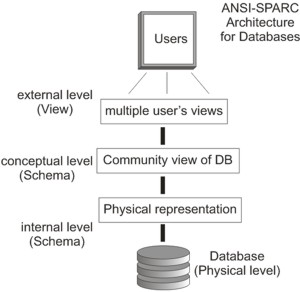 |
What they came up with is shown at the right. There were several objectives to this methodology. First, this architecture allows for each user to see the data she wants or needs in the way she needs it to show up. Second, it removes the physical storage details from the user. Third, the Data Base Administrator [DBA] can maintain the schema without having to worry [too much] about affecting the users' views of the data. Finally, the internals of the server will not affect the data or views. |
From the top, the levels and their meanings/descriptions are:
- External or user or view level: this view describes the part of the database that is actually relevant and pertinent to the users' applications. Multiple users can have different views of the same [or different] data without affecting either each other or the data itself. Also, this allows the same user to look at the same data in different ways.
- Conceptual or community view level: this level supplies a way of describing what data is
stored within the entire database, how that data is
grouped
together and/or associated, and how it is related to other data in the same tables/relations/database. This concept is also known as thedatabase schema
. Note that the conceptual level includes BOTH the conceptual level as a view AND the internal level as a representation, which we'll get to later [we're talking diagrams here…] - Internal level: at this level, the actual physical storage of the data on the hard disk of the server on which the data is stored is taken into account. At this level, [lucky for us!!] only the designers and implementers of the DBMS are really involved. Unless you go to work for Oracle, IBM, Microsoft, Google, Amazon, or some other major corporation as a database designer or implementer, or have need to optimize query implementations, you'll probably never see this level's details. Still, it's good to know it's out there, abstracted away by this model, and making it easy for us to do our implementations without having to worry about these devilish details.
Entities / Attributes / Relations
OK, so since we don't need to work at the physical level, what we need to focus on as database design engineers is the second level, the schema. There are several important things to remember about this particular level. First, this level provides a global view of the database, meaning that one can see the entire thing at the same level [within the contsraints of the diagram, of course]. Second, this level defines the structure of the database for ALL USERS. At this level, the data representation is the same for everyone that uses the database, from normal dumb users to the most sophisticated DBA. At this level, the data is totally generic. Finally, only the DBA can define the schema at this level, and only s/he can work with the data at this level, for obvious reasons.
So, in the database parlance of our times
, we often refer to database tables
as the things that are contained in the database. We
mean by this that the database is made up of a bunch of things
that have columns, with rows of data
that fit into those columns. However, this is the lazy slang way to refer to things. The actual
nomenclature is that the database is composed of entities, with each entity having
certain attributes. Try, if you can, to train yourself to use these words instead.
Finally, in certain circumstances [which will be discussed in a bit] there are separate entities that
link
entities together; these are known as relations, because they relate
the entities to each other. Indeed, this is where the idea of a relational
database came from.
This next section will provide some details and examples of these three concepts, and different ways of showing them via diagrams.
Diagrams for Databases – the Entity-Relationship Diagram [ERD]
Now that we know the preferred nomenclature, we can take a look at how to model the database. The standard
model used is called the Entity-Relationship Diagram
, or just ERD
. There
are three main ways to draw this diagram. The first way, which isn't used much any longer, is part of the
Unified Modeling Language which is a specification that has all kinds of diagrams and modeling
tools
that allow anything from top-level to extremely detailed representaitons of the software
system. The second way is known as the Crows Foot Model
, because some of the parts
of the diagram reminded someone a long time ago of a bird's foot. Finally, there is the Chen
model, named after the person who came up with it.
The first one we'll look at is the Crow's Foot. A handy-dandy sheet of the diagrammatic components can be found here.
The second one we'll dissect is the Chen model. Another handy-dandy not-so-quick reference to this model can be found at this location. A second reference to the model from a different source can be had from this link.
One more term that you need to know is the word SCHEMA
which is a fancy name for
the design of the database. Everything that goes in there is part of the schema
of the database. Each of the entities contains multiple attributes, and the values of the attributes in
each entity are it's tuples, a term you should remember from several other courses. Each tuple in
an entity represents a record
in the database. In the vernacular, the entities are
called tables, the attributes are called columns, and the records or tuples are called
rows. Let's see how all this goes together.
We're going to use SqlFiddle as our demonstrator.
Schemas – Defining Data Definition Language [DDL] and Diagrams
When we create a database schema, we define and describe the entities and their attributes that belong to that database. For example, let's say we are defining a horse racing database. We might have horses, jockeys, and owners. We might have stables. We could have races. There could be any number of other entities that we can define, based on what data we are interested in keeping track of in our database.
Any entity will have natural things that make up that entity, which is where attributes come into the picture. Each entity will have at least one attribute, although only having one makes the representation of that entity somewhat less than useful [IMHO]. [NOTE: think of an object, then think of possible attributes for that entity and write them in a list.]
The SQL statements that define the entities and their attributes are known as Data Definition
Language
or DDL. There are several statements that belong in this category, the most notable
being the CREATE and the
DROP statements. CREATE creates an entity, and
defines the attributes that belong to or comprise that entity [we've seen this before]. For example:
   CREATE TABLE Horses
      (horse_id         int            NOT NULL
      ,horse_name       varchar(50)    NOT NULL
      ,owner_id         int            NOT NULL
      ,horse_age        int
      ,horse_height     int
      ,number_of_races  int
      ,last_race_date   date
      ,last_race_won    date
      );
The DROP SQL statement is trivial: DROP TABLE Horses. However, note that there may be situations for which special conditions apply for dropping tables. An example is trying to drop a table that doesn't exist. This happens when you are creating a database using scripts to drop the old versions of tables, then creating and loading new versions of them.
A related SQL statement is the TRUNCATE TABLE
statement which simply empties the table without
deleting the table itself.
Another DDL statement is the ALTER statement, which modifies an existing entity. This command is used to add or remove attributes to an entity. CARE MUST BE TAKEN when doing this to preserve the data. Often the entity alteration is not really feasible for several reasons.
Finally, there is the RENAME statement, which will simply rename an entity in the database. Again, however, caution should be used, since there may be other entities, views, or scripts in the database that rely on a specific name for an entity, such that if the name is changed, things will no longer operate correctly. Using RENAME should be treated as a re-factoring exercise.
Schemas – Data Manipulation Language [DML] and SQL F'realz
OK, next we need to be able to do things like add data, remove data, change and update data and so
on, which is known as Data Manipulation
. There are several SQL statements to accomplish such
operations.
First there is the INSERT statement, which is used to put data into an entity. There are several ways to do this. You can insert data for all of the attributes, or any subset of them. Also, the attributes don't have to be in the specific order that they are defined in the CREATE statement. Here's an example:
   INSERT INTO Horses
   VALUES
       (1,  'Banana',     'John Smith',        3,  16,  5,  '2017-02-14',  NULL)
      ,(2,  'Girdle',     'Joan Cuzak',        3,  16,  6,  '2017-03-17',  '2017-03-17')
      ,(3,  'Beetlebaum', 'Lynnerd Skinnerd',  2,  17,  1,  '2017-04-01',  '2017-02-14');
Notice that in this example we are specifying ALL ATTRIBUTES, and they just happen to be in the order that they are created in the CREATE statement. Here is another way to do it:
   INSERT INTO Horses
      (horse_id, horse_name, horse_age, horse_height)
   VALUES
       (1, 'Banana',     3,  16)
      ,(2, 'Girdle',     3,  16)
      ,(3, 'Beetlebaum', 2,  17);
In this case, we have simply entered each horse's vital statistics of index, name, age, and height, and have just left the rest blank. Here's another way to do this:
   INSERT INTO Horses
      (horse_age, horse_name, horse_id, horse_height)
   VALUES
       (3,  'Banana',     1,  16)
      ,(3,  'Girdle',     2,  16)
      ,(2,  'Beetlebaum', 3,  17);
So, as long as the data match the order of the attributes as we list them in the command, it's all good. If we get things out of order, though, we may get chaos, or we may get an error. SQL is a statically typed language, so if we try to put an integer into a date, or a float into an integer, there will be an error message resulting. CAVEAT: this may not ALWAYS be the case, such as when loading a string data type. There are many things that use the single-quoted string, so something may actually get loaded even if it is not the correct data, if it is in single quotes!
Cardinality
This is one of the simplest concepts of the whole thing. Cardinality is just a fancy name that is given to the idea that there are countable relationships between entities. There are three types:
- One to one: each record in an entity refers to one record in another entity. An example of this might be you and your student ID.
- One to many: each record in an entity refers to many records in another entity. A way of looking at this is that there is only one Keck lab, but it has many computers in it.
- Many to many: each record in an entity refers to one record in another entity. For instance, you as a single student have many classes which you have taken, and each class can have many students enrolled.
In-class Exercise
Here are two definitions of a database. You will create an Entity Relationship Diagram from these descriptions. We'll then discuss how these entities link together, and you'll get some experience in the actual design process. I'll be throwing out thoughts about things that need to be considered as you are designing, as well, and I [of course] invite suggestions and questions from the rest of the class membership. You will work in teams of two or three [at least, more is OK]. I'd like at least a couple of teams to work on the whiteboard, while the remaining teams work at the tables. Feel free to move to the Annex if you wish! Also, feel free to do more than one for the practice.
Here is one design statement [which can be treated as a quasi-requirements document
]:
Anassetis a piece of equipment that is a physical device of some kind. It may be a computer, a piece of test equipment like a multimeter, a piece of software, an end-user license, or a network. An asset may belong to another asset, as part of an asset hierarchy. All assets will have:
- AssetIndexID: an integer number which is the index of the asset record
- AssetID: a string [maximum 15 characters] that uniquely identifies the asset
- AsBuiltRevision: a string [maximum 25 chars] that contains the current build revision info
- AssetTypeIndexID: an integer indicating the asset type
- PreviousRecord: an integer which contains the assetIndexID of the record which holds the immediately previous version of this asset
- SerialNumber: a string [50 chars max] holding serial number information for the asset
- LastCalDate: date of the last calibration due on this asset
- CalDueDate: date of the next calibration due on this asset
- CalRequired: flag variable set to
trueif calibration is required- LastPMDate: date of the last preventive maintenance performed on this asset
- PMCycleDurationDays: integer of the number of days between PM cycles
- PMRequired: flag variable set to
trueif preventive maintenance is required- LocationIndexID: index of the building and room number location of this asset
- AssetDescription: a short [30 char max] word description of this asset
- AssetDetailDescription: a detailed [255 char max] description of this asset
- StatusIndexID: index into the status table reflecting the current asset status; one of: ready, broken, in-calibration, retired, or in-use.
- LogicalName: a string [50 chars max] that describes the logical system name of the asset
- NetworkEnabled: flag variable indicating if the asset is network [TCP/IP] enabled
- PartNumberIndexID: integer index into the part number table for the part number associated with this asset
Apartentity reflects a numbered part reference which may or may not be attached to or associated with an asset. Part numbers have the following attributes:
- PartNumberIndex: integer number which is the index of the part number record
- PartNumber: a string [50 chars max] that contains the part number
- Manufacturer: a string [50 chars max] which contains the part's manufacturer name
- ModelNumber: a string [50 chars max] which contains the manufacturer model number for this part
- AsDesignedRevision: a string [10 chars max] contining the current design revision info
- PartDescription: a string [100chars max] containing a brief description of the part
- CommonName: a string [20 chars max] containing the
common nameby which this part is known- PartCategoryem>: a string [50 chars max] which contains the category of the part; one of: Proprietary, Purchased, Company-built
- DetailedTextDescription: string [255 chars max] containing a detailed description of a part
All parts are assets, but not all assets are parts.
Assets are used for various operations, and a history log must be kept for each time an asset is used. Thehistory logwill have an integer ID number which is the primary method of identifying each entry. Each entry will be linked to an asset by an integer LinkedAssetID attribute, and will also include the 6-digit Employee ID of the person making the entry, along with the date of the entry, both of which must be included. An entry type is also a required part of the history, and must be one of: information, status, or change-request.
Here is a second design statement:
Entities
APRODUCTis supplied by aSUPPLIERto the customers using aPURCHASE ORDER. A PRODUCT has the attributes product name, product type, available quantity, and product number. A SUPPLIER has the attributes supplier number, supplier name, address, phone number, city, state, zip code, and hours [which indicates the number of hours in a business day that the supplier is open/available]. A PURCHASE ORDER has the attributes order date, order amount, customer name, order ID number, shipping address [which includes street, city, state, and zip code], and contact name.
Relationships
A supplier can supply minimum zero and maximumNproducts. A product is supplied by minimum zero and maximumMsuppliers. The SUPPLIES relationship type has two attribute types:purchase priceanddelivery period, representing the price and period for a particular supplier to supply a particular product. A supplier has minimum zero and maximumNpurchase orders on order. A purchase order is on order with minimum one and maximum one – in other words, exactly one – supplier. PURCHASE ORDER is existence dependent on SUPPLIER. A purchase order can have several purchase order lines, each for a particular product. This is the relationship type between PURCHASE ORDER and PRODUCT. A purchase order can have minimum one and maximumNproducts as purchase order lines. Vice versa, a product can be included in minimum zero and maximumNpurchase orders. The relationship type is characterized by the quantity attribute type, representing the quantity of a particular product in a particular purchase order.
Here is a third optional one if you want more practice. Here are the major characteristics of a banking enterprise:
- The BANK is organized into BRANCHES. Each branch is located in a particular city, and is identified by a unique name. The bank monitors the assets of each branch.
- Bank CUSTOMERS are identified by their customer ID values. The bank stores each customer's name, and the street and city where the customer levies. CUSTOMERS may have accounts and can take out loans. A CUSTOMER may be associated with a particular BANKER, who may act as a loan officer or personal banker for that customer.
- Bank EMPLOYEES are identified by their employee ID values. The bank administration stores the name and telephone number of each employee, the names of the employee's dependents, and the employee ID number of the employee's MANAGER. The bank also keeps track of the employee's start date and, thus, the length of employment.
- The bank offers two types of ACCOUNTS – savings and checking accounts. ACCOUNTS can be held by more than one CUSTOMER, and a CUSTOMER can have more than one ACCOUNT. Each account is assigned a unique account number. The bank maintains a record of each account's balance, and the most recent date on which the account was accessed by each customer holding the account. In addition, each savings account has an interest rate, and overdrafts are recorded for each checking account.
- A LOAN originates at a particular BRANCH and can be held by one or more CUSTOMERS. A loan is identified by a unique loan number. For each loan, the bank keeps track of the loan amount and the loan payments. Although a loan-payment number does not uniquely identify a particular payment amount those for all the bank's loans, a payment number DOES identify a particular payment for a specific loan. The date and amount are recorded for each payment.
Coming up…
- 'Tables', Keys, and Normalization
- ACID and CRUD
- Constraints and Stored Procedures
- More SQL Language
- MySQL
- PostGreSQL