
The following is an example of the Architectural Design Document from a previous CMSI 401 project, which you can use as an example of the level of detail expected. Notice that the diagrams at the bottom of the document are very high-level, as are the class explanations. However, there are sections for every class and method that are expected to be included in the entire project.
Remember: this is an iterative process. All software engineers are expected to "re-visit" their documentation during development to make sure it is correct, meaning it matches the current implementation. If your project ends up not needing one of the classes or methods you have documented, it is extremely unhelpful to later maintainersc if the documentation still shows that method as part of the project. This is one of the reasons that modern projects use some form of automated documentation generator, like javadocs, autodoc, or doxygen.
6.0 RAPID Architectural Design
6.1 Introduction
This document presents the Architectural Design for the RAPID project. RAPID is an integrated, GUI-driven, Product database management system, allowing users to query a database, determine if a product is available for sale, the quantity, price, and status of all products and components, coupled with an automated entry system using a barcode scanner. Multiple client connections to the database are supported, along with client account validation via a login and password.
6.1.1 System Objectives
The goals of this project are to provide a user-friendly, comprehensive system for inventory management. As a model, the project uses a small bottling plant enterprise. Products in the system are comprised of various components, so each product has a specific list of components which must all be present in the inventory in sufficient quantity to create the desired amount of product for any order. Components may belong to more than one product. If a component for a product is out of stock, or is back-ordered, the entire product is considered to have the same status – thus products are inter-related.
6.1.2 Hardware, Software, and Human Interfaces
The hardware interfaces for this project consist of a TCP/IP network, such as the internet or a LAN. Also, a bar-code reader and it's appropriate interface (usually either a serial port or a USB port are required) will be needed to scan incoming and outgoing products and their components. Networking between clients and the server is accomplished via standard Berkeley Socket interfacing. Wireless networking is not directly supported, but is not precluded in the design. The server is threaded to handle multiple connections, and uses a system of "callbacks" to handle functions for all buttons and indicators.
6.2 CSCI Descriptions
Three CSCs compose the RAPID system CSCI, as follows:
- The Client CSC
The Client is composed of several classes, each of which performs a set of functions. All functions are hierarchical in nature, meaning the functions in any level are a subset of the functions of the next-higher level, and a superset of the next-lower level. (I'd put more here, but you get the idea.)
The Client CSC is composed of the following CSUs:
- Salesperson GUI CSU — used to access sales information by order number, and to create new orders for a customer on site. Also allows access by customer number.
- FloorSupport GUI CSU — used to access all information available to the Salesperson GUI level, with additional functionality to use the bar code reader for scanning in components, and for scanning out products.
- Administrator GUI CSU — used to access all functions of the system, including the creation and modification of user accounts. May also be used to override order status in the event of customer preferences.
- Interface class CSU — used establish and maintain connections to the server, and to send and receive query and response messages to the database via the server.
- The Server CSC
There are no classes in the RAPID server code. The server is implemented using the LabWindows/CVI programming environment. This application uses "vanilla 'C' code" in a windowing development environment with an integrated compiler, linker, and debugger. When coupled with the extensive sample code provided with the installation, this provides an extremely fast and flexible development environment which minimizes cycle time while providing functionality to maximize robustness in developed applications.
- Server GUI CSU &mdash used to display the server control GUI, including indicators to monitor up to ten client connections, and buttons to reset any connection which has become corrupted.
- Server Functions CSU — a set of files containing the callback functions attached to the button and indicators.
- The Database CSC
There are no classes in the RAPID database API code. This segment of RAPID is also developed with the LabWindows/CVI environment. To simplify database connectivity, the ODBC connections of the CVI SQL Toolkit will be used. This provides the same fast and flexible development environment for database access as the LabWindows/CVI environment provides for the server code, as outlined in the preceding paragraph.
- Database Interface CSU — used to interface the database with the server so as to speed connectivity with the connected clients.
- Database Access CSU — used to translate the proprietary message format into standard SQL query format for use in accessing the product database.
The Server CSC is composed of the following CSUs:
The Database CSC is composed of the following CSUs:
6.2.1 Concept of Execution
The RAPID system execution begins with starting the Microsoft Access Database. Once this part of the application is active, the RAPID server can be started. Server initialization will automatically connect to the database, and will display a GUI to the user to allow monitoring of up to ten client connections. At this point, a client may connect to the system from any terminal capable of running a Java application.
The client initialization requires logging in to the system, via a log in screen which appears at startup. Successful access validation will cause the appropriate level client GUI screen for that user to be displayed. Client accounts are assigned their access levels by the system administrator, who also must have an account on the system. The GUI screens for accounts thus differ by the level of account access assigned. Once the client has connected, any function which is available on the screen can be used to access the database. Queries for products are available, using drop down lists. When a product is selected, all remaining fields of the display are filled in with lists of components for that product, availability for the product and all components, and backorder status where applicable. The client screen can also be used to track an order by order number, or to submit an entirely new order. In the latter case, if insufficient quantities of any component are available to complete the order, the operator is notified and provided an opportunity to modify or cancel the order.
6.2.2 Interface Design
The following sections provide detail of the different interfaces between the segments of the RAPID project. (This example is minimal, just to give you an idea, and as this project didn't use UML for its diagrams, it's not technically correct; you get the idea.)
6.2.2.1 Interface Identification and Diagrams
6.2.2.1.1 Client Class and Function Modules
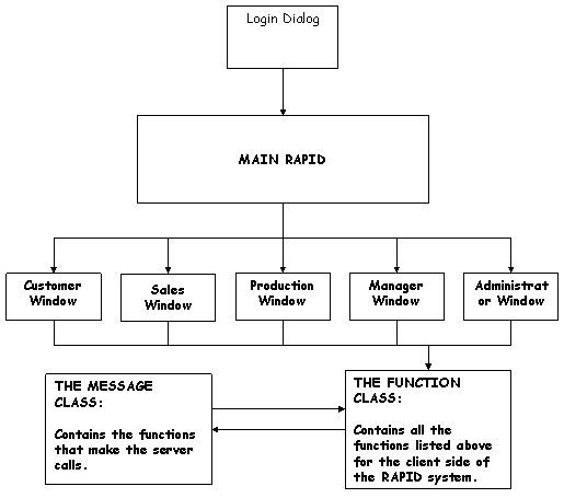
Figure 9.1: RAPID Client Class and Functional Diagrams
6.2.2.1.2 Server and Database API Modules
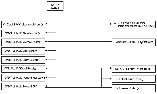
Figure 9.2: RAPID Server and Database API Functional Diagrams
6.2.2.2 Project Interactions
A proprietary messaging format is developed for use in communications within the RAPID project. The message format consists of a stream of bytes, which are defined as follows:
- A 4-byte integer value containing the message type
- A 4-byte integer value containing the message length
- An n-byte message string which is the length of the value of the second field
The various message formats are contained in the message field and will be interpreted based on the value of the first field. The method is to read the first two integers for every message, interpret the number of bytes to read after that, and read that many bytes from the socket. when all bytes have been successfully read, the message is interpreted by "casting" it to the proper structure internal to the client or server.
6.3 Preliminary User Manual
Actually, I'll leave this to your imagination — I won't do all the work for you!